| 8.22. Mixeur de canaux | ||
|---|---|---|

|
8. Le menu « Couleurs » |  |
| 8.22. Mixeur de canaux | ||
|---|---|---|
|
|
8. Le menu « Couleurs » | |
Figure 16.160. Exemple pour la commande « Mixeur de canaux »
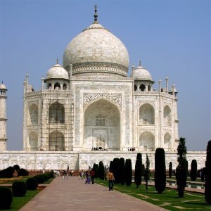
Image d’origine
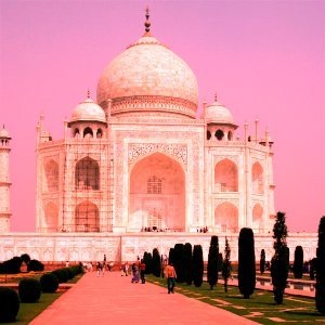
Après application de la commande « Mixeur de canaux »
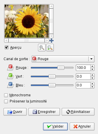
This command combines values of the RGB channels. It works with images with or without an alpha channel.
« Presets » are a common feature for several Colors commands. You can find its description in Section 8.1.1, « Fonctions communes aux couleurs ».
Each of these has three sliders, which set the contribution of the red, green and blue input channels in the output channel. The sliders go from -2 to 2. They represent the multiplication factor of the input channel that will be attributed to the output channel.
The mixing can result in an image where some of the colors are too light. This option lessens the luminosity of the color channels while keeping a good visual ratio between them. So, you can change the relative weight of the colors without changing the overall luminosity.
These are common features described in Section 8.1.1, « Fonctions communes aux couleurs ».
Each of the output channels is based on the values you set for the three RGB input channels. By default each output channel is based for 100% on the corresponding input channel. This is the one set to 1.0, and the others are set to 0.0. You can change each of the sliders from -2 to +2.
The three RGB input sliders let you give a percentage to every channel. For every pixel in the image, the sum of the calculated values for every channel from these percentages will be given to the output channel. Here is an example:
Figure 16.162. L’image d’origine et ses canaux
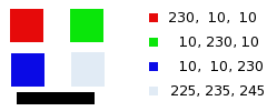
RGB values of the pixels in red, green, blue, gray squares are displayed. The black rectangle is special, because black (0;0;0) is not affected by the command (0 multiplied by any percentage always gives 0). The result can't exceed 255 nor be negative.
Figure 16.163. Canal de sortie: rouge. Canal Vert +50%
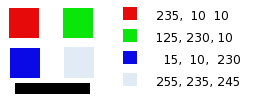
Dans le carré rouge, les pixels ont pour valeur 230;10;10. Les pourcentages sont 1;0,5,0. Le résultat du calcul est 230*1 + 10*0,5 + 10*0 = 235. Le même raisonnement vaut pour les carrés vert et bleu.
Pour le carré gris, qui contient la couleur rouge, la valeur calculée est largement supérieure à 255: elle est bloquée à 255. De même, une valeur négative serait bloquée à 0.
Figure 16.164. Canal de sortie: rouge. Canal Vert +50%. L’option Préserver la Luminosité est cochée.
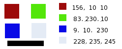
The values attributed to the Red Output channel are lower, preventing a too bright image.