| 12.7. Map Object | ||
|---|---|---|
 |
12. Map Filters |  |
| 12.7. Map Object | ||
|---|---|---|
| |
12. Map Filters | |
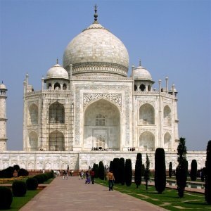
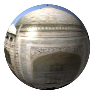
This filter maps a picture to an object (plane, sphere, box or cylinder).
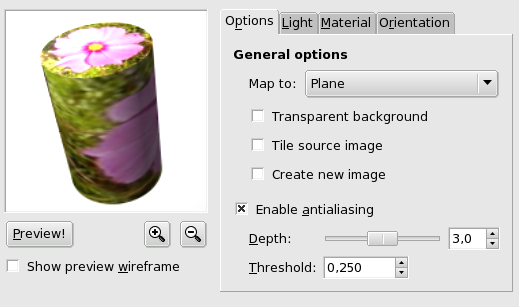
This preview has several possibilities:
: Preview is automatic for some options but you will have to press this button to update Preview after modifying many other parameters.
When mouse pointer is on Preview and the Light tab is selected, it takes the form of a small hand to grab the blue point which marks light source origin and to displace it. This blue point may not be visible if light source has negative X and Y settings in the Light tab.
allow you to enlarge or to reduce image in Preview. Their action is limited, but may be useful in case of a large image.
Show Preview Wireframe: Puts a grid over the preview to make displacements and rotations more easy. Works well on a plan.
This drop-down list allows you to select the object the image will be mapped on. It can be a Plane, a Sphere, a Box or a Cylinder.
This option makes image transparent around the object. If not set, the background is filled with the current background color.
When moving Plane object and displacing it with Orientation tab options, a part of the image turns empty. By checking the Tile source image, source image copies will fill this empty space in. This option seems not to work with the other objects.
![[Note]](images/note.png)
|
Note |
|---|---|
|
This option works with “Plane” only. |
When this option is checked, a new image is created with the result of filter application, so preserving the original image.
Check this option to conceal this unpleasant aliasing effect on borders. When checked, this option lets appear two settings:
Depth: Defines antialiasing quality, to the detriment of execution speed.
Threshold: Defines antialiasing limits. Antialiasing stops when value difference between pixels becomes lower than this set value.
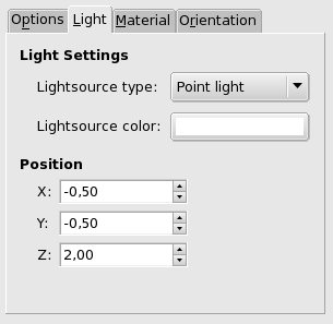
Lightsource type: In this dropdown list, you can select among Point light, Directionnal light and No light.
Lightsource color: Press this button to open the Color Selector dialog.
If “Point light” is selected, you can control there light source Position (the blue point), according to X, Y and Z coordinates.
If “Directional light” is selected, these X, Y and Z parameters control the “Direction vector” (effect is not evident).
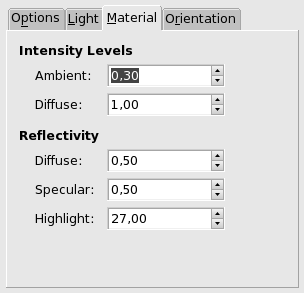
Ambient: Amount of color to show where no light falls directly.
Diffuse: Intensity of original color when lit by a light source.
Diffusion: Higher values make object reflect more light (looks brighter).
Specular: Controls how intense the highlights will be.
Highlight: Higher values make the highlights more focused.
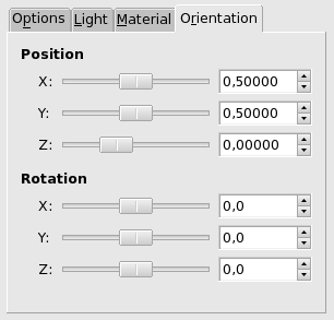
These three sliders and their input boxes allows you to vary object position in image, according to the X, Y, Z coordinates of the object upper left corner.
These three sliders make the object rotate around X, Y, Z axes respectively.
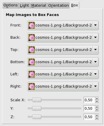
This tab appears only when you select the Box object.
This function name is self explanatory: you can select an image for every face of the box. These images must be present on your screen when you call the Map Object filter.
These X, Y, Z three sliders allow you to change the size of every X, Y, Z dimension of the box.
This tab appears only when you select the Cylinder object.
The name of this option is self-explanatory. Images must be present on your screen when you call the Map Object filter.
Radius: This slider and its input boxes let you control the Cylinder diameter. Unfortunately, this setting works on the image mapped onto the cylinder and resamples this image to adapt it to the new cylinder size. It would be better to have the possibility of setting size cylinder before mapping so that we could map a whole image.
Length: Controls cylinder length.