| 13.3. Displace | ||
|---|---|---|

|
13. Map Filters |  |
Rysunek 17.286. Displacement examples
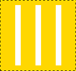
Original image

The displacement map has four gray stripes with values of 210, 160, 110, and 60, respectively.

Horizontal displacement coefficient is 30. Vacated pixels are black. The image areas corresponding to light gray (128) were displaced 19 and 8 pixels to the left. The image areas corresponding to dark gray (127) were displaced 4 and 15 pixels to the right.
This filter uses a „displace-map” to displace corresponding pixels of the image. This filter displaces the content of the specified drawable (active layer or selection) by the amounts specified in Horizontal and vertical Displacement multiplied by the intensity of the corresponding pixel in the „displace map” drawables. Both Horizontal and Vertical displace maps should be grayscale images and have the same size as the drawable . This filter allows interesting distortion effects.
![[Uwaga]](images/note.png)
|
Uwaga |
|---|---|
|
These options are described in Sekcja 2, „Common Features”. |
Clicking on a question mark button opens a small file browser with two panels. The left panel shows images present on your screen. The right panel shows the layers of the selected image. Double click on the wanted layer to select the map.
You can select different maps for Horizontal and Vertical displacements.
You can choose working in Cartesian coordinates, where pixels are displaced in Horizontal or Vertical direction, or working in Polar coordinates, where the image is pinched and whirled by displacing pixels in radial or tangent direction.
Please see the next sections for details about these options.
Interpolation methods are described in Transform tools
These options allows you to set displacement behavior on active layer or selection edges. They are described in Abyss policy
Rysunek 17.288. Displace filter options (Cartesian)
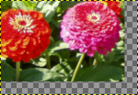
Horizontal and vertical displacements are 20 pixels
In both modes, direction and amount of displacement depend on the intensity of the corresponding pixel in the displacement map.
The map, that should be a grayscale image, has 256 gray levels (0-255), the (theoretical) average value is 127.5. The filter displaces image pixels corresponding to pixels with values less than 127.5 (0 to 127) in map to one direction, corresponding to pixels with values from 128 to 255 to the opposite direction.
If the respective option is activated, image pixels corresponding to pixels from 0 to 127 will be displaced to the right for Horizontal, downwards for Vertical, image pixels corresponding to pixels from 128 to 255 will be displaced to the left for Horizontal, upwards for Vertical.
What you enter in input boxes, directly or by using arrow-head
buttons, is not the actual displacement. It's a coefficient used
in a
 formula, which gives the pixel actual displacement according to
the scaled intensity
[13]
of the corresponding pixel in map, modulated by the coefficient
you enter. Introducing intensity into formula is important: this
allows progressive displacement by using a gradient map.
This value may be positive or negative. A negative displacement is reverse of a positive one. The value varies in limits equal to the double of image dimensions.
When you click on the drop-down list button, a list appears where you can select a displacement map. To be present in this list, an image must respect two conditions. First, this image must be present on your screen when you call filter. Then, this image must have the same dimensions as the original image. Most often, it will be a duplicate original image, which is transformed to gray scale and modified appropriately, with a gradient. It may be possible to use RGB images, but color luminosity is used making result prevision difficult. Map may be different in horizontal and vertical directions.
If this option is activated, the radial coordinates (i.e. the distance to the image's midpoint, the „pole”) of the pixels will be changed. Image pixels corresponding to map pixels from 0 to 127 will be displaced outwards, image pixels corresponding to pixels from 128 to 255 will be displaced towards center.
For the values and the displacement map see above („Horizontal/Vertical displacement”).
The displacement is independent from the polar distance, all pixels are displaced by the same amount. So the image will not only be stretched or compressed, but also distorted:
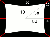
Image distortion by Pinch option
A 160×120 pixels image, plain white displacement map, and displacement coefficient 20.0: this results in a 20 pixels displacement towards center. This is a horizontal reduction in size by 25%, vertical by 33%, and diagonal by 20%, so the image will be distorted.
If this option is activated, the angular coordinates of the image pixels will be „displaced” by a map pixel dependent amount. For a plain displacement map, the image will be rotated, otherwise it will be whirled.
Image pixels corresponding to pixels from 0 to 127 in the map will be displaced counterclockwise, image pixels corresponding to pixels from 128 to 255 will be displaced clockwise.
For the values and the displacement map see above.
![[Uwaga]](images/note.png)
|
Uwaga |
|---|---|
|
For a plain, non neutral map, if displace mode „Polar” is enabled, this filter works like Whirl and Pinch. |
Follow following steps:
Start with opening your image.
Duplicate this image. Activate this duplicate and make it grayscale ( → → ). Fill it with the wanted gradient. This image will be your Displacement map, with the dimensions of original image.

Activate original image. Create a Text Layer with your text. Set layer to image size: right-click on the layer in Layers dialog and, in the pop-up menu, click on „Layers to image size”. Note that letters in text layer lie on a transparent background; now this filter doesn't displace transparent pixels. Only letters will be displaced.

Activate the text layer. Open the Displace filter window. Set parameters, particularly the displacement coefficient, according to the result in Preview. Click OK.
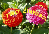
This method also applies to standard layers:

![[Podpowiedź]](images/tip.png)
|
Podpowiedź |
|---|---|
|
To get the wanted gradient, first draw a black to white gradient. Then use the Curves tool to modify the gradient curve. |
Follow following steps:
Open the image with an uneven texture.
Create the map: Duplicate the image. Then select → → .
Create the text in Texture image. Move it if necessary. Make this text layer the same size as the image via Layers to Image Size.
Open the „Displace” filter. Click on the button and double-click on the map image thumbnail in the left panel.

Displace filter applied.
The following section will show you how to calculate the amount of displacement, if you are interested in these details. If you don't want to know it, you can safely omit this section.
The overview example showed the horizontal displacement using a coefficient of 30.0: 19, 8, 4, or 15 pixels, depending on the gray level of the displacement map's color.
Why just these amounts? That's easy:


If you check these equations, you will notice that the values they give are not exactly the results we retained in the example (using non-integers, that's not surprising). So, were the results rounded to the nearest integer and then the pixels were displaced by a whole-numbered amount? No. Every pixel is displaced exactly by the calculated amount; a „displacement by a fractional amount” is realized by interpolation. A closer look at the example image will show it:
The displacement causes small (one pixel wide) areas of intermediate colors at the edges of plain color areas. E.g., the black area (zoomed in image) is caused by a displacement of -4.12, so the intermediate color is 12% black and 88% gold.
So if you select a displacement coefficient of 30.01 instead of 30.00, you will indeed get a different image, although you won't see the difference, of course.