Con il comando , è possibile posizionare in maniera precisa i livelli visibili (quelli marcati con l'icona a forma di «occhio»). Questo livello di precisione è utile in special modo quando si sta lavorando con le animazioni, che tipicamente sono formate da molti piccoli livelli. Facendo clic su viene mostrata una finestra di dialogo che permette di scegliere come dovranno essere allineati i livelli.
-
You can access this command from the main menu through → . There is no default keyboard shortcut. If the image holds a single layer only, you get a message from GIMP telling that there must be more than one layer in the image to execute the command.
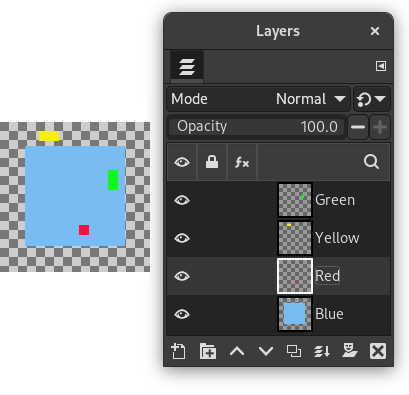
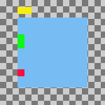
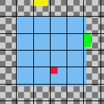
The examples in the Description of the “Align Visible Layers” dialog section all use the same starting image. The image contains four layers. The order of those layers from top to bottom is as follows:
-
Green, vertical rectangle (top layer)
-
Yellow, horizontal rectangle
-
Red, small square
-
Blue, larger square (bottom layer)
The command aligns layers based on their boundaries. In the example image, each layer's boundary is adjusted to match the perimeter of the shape in that layer. For information about how to adjust a layer's boundary, see Layer Boundary Size. You can also use a command such as Crop Layers to Content to automatically adjust a layer's boundary.
![[Nota]](images/note.png)
|
Nota |
|---|---|
|
In the examples, the Ignore the bottom layer even if visible checkbox is left checked. The bottom layer, which is the larger blue square, is then not affected by any of the alignment operations. |
- Horizontal style, Vertical style
-
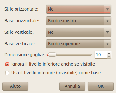
Queste opzioni controllano come i livelli debbano essere spostati in reciproca relazione. È possibile scegliere tra gli stili:
-
Nessuno: non ci saranno cambiamenti nella posizione orizzontale o verticale dei livelli.
-
Seleziona: tutti i livelli visibili verranno allineati sulla superficie disegnabile, nella modalità determinata dalle opzioni base orizzontale e base verticale. Se si seleziona base orizzontale di bordo sinistro, dei livelli potrebbero sparire dalla superficie. È possibile ripristinarli allargando la superficie di disegno. Se si imposta l'opzione usa il livello inferiore (invisibile) come base, i livelli saranno allineati all'angolo in alto a sinistra del livello in fondo alla pila.
Figura 16.73. Example Use of Collect: Layers Aligned to Left Edge of the Canvas
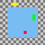
Immagine originale
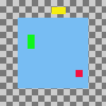
Horizontal style: Collect , Horizontal base: Left edge.
I livelli sono stati spostati orizzontalmente in modo tale che i loro bordi sinistri siano allineati con il bordo sinistro della superficie disegnabile.
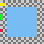
Figura 16.74. Example Use of Collect: Layers Aligned to Left Edge of the Bottom Layer
Immagine originale
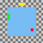
Same parameters as the previous example, but with the Use the (invisible) bottom layer as the base checkbox checked.
I livelli sono stati spostati orizzontalmente in modo tale che i loro bordi sinistri siano allineati con il bordo sinistro del livello in fondo alla pila.
-
Fill (left to right); Fill (top to bottom): The visible layers will be arranged left to right (or top to bottom) on the canvas according to their order in the layer stack.
The top layer in the stack will be aligned with the layer that currently has the leftmost (or uppermost) position on the canvas. The bottom layer in the stack will be aligned with the layer that currently has the rightmost (or bottommost) position on the canvas. All other visible layers will be evenly distributed between those two positions according to their order in the layer stack.
Your choice of Horizontal base (or Vertical base) determines how the top and bottom layers are aligned with their respective target layers. For example, if you choose Right edge as the Horizontal base, the right edge of the top and bottom layers will be aligned with the right edge of their target layers.
Nota If the Use the (invisible) bottom layer as the base checkbox is checked, the top layer in the stack will be aligned with the current position of the bottom layer in the stack, instead of the leftmost (or uppermost) layer on the canvas.
Figura 16.75. Example Use of Fill: Layers Filled Left to Right
Immagine originale
Horizontal style: Fill (left to right), Horizontal base : Left edge.
The top layer in the stack, the green one, was aligned with the layer that had the leftmost position on the canvas. The bottom layer in the stack, the red one, was aligned with the layer that had the rightmost position on the canvas. The yellow layer is placed between the other two.
Figura 16.76. Example Use of Fill: Layers Filled Left to Right With the Bottom Layer as the Base
Immagine originale
Same parameters as the previous example, but with the Use the (invisible) bottom layer as the base checkbox checked.
The top layer in the stack, the green one, is aligned with the left edge of the base layer. The bottom layer in the stack, the red one, was aligned with the layer that had the rightmost position on the canvas. The yellow layer is placed between the other two.
-
Riempi (destra sinistra); Riempi (basso alto): queste impostazioni lavorano in maniera simile a quelle descritte sopra, ma il riempimento funziona nella direzione opposta.
Figura 16.77. Example Use of Fill: Layers Filled Bottom to Top With the Bottom Layer as the Base
Immagine originale
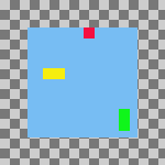
Vertical style: Fill (bottom to top), Vertical base : Top edge, Use the (invisible) bottom layer as the base: checked.
The bottom layer in the stack, the red one, is aligned with the top edge of the base layer. The top layer in the stack, the green one, was aligned with the top edge of the of the layer that had the lowest position on the canvas. The yellow layer is placed between the other two.
Ci devono essere minimo tre livelli visibili nell'immagine per poter usare le opzioni di «Riempimento».
-
Snap to grid: The visible layers will be aligned with a grid. Use the Grid setting to define the spacing of the grid. The base that you select will be aligned with its closest grid line. For example, if you select Left edge from the Horizontal base list, the left edge of each layer will be aligned with the grid line that is closest to the layer's left edge.
In the following example, the image grid is turned on and its spacing set to the same value as the Grid setting. This is only to help demonstrate the effect of the Snap to grid option. You don't need to turn on the image grid and none of its settings are used when you align layers.
Figura 16.78. Example Use of Snap to Grid: Layers Aligned to Top Left Corner of Grid Squares

Original image with an added 30 pixel image grid
Horizontal style: Snap to grid, Horizontal base: Left edge, Vertical style : Snap to grid, Vertical base: Top edge , Grid: 30
Each layer other than the base is aligned with the top left corner of a 30 by 30 pixel grid square.
-
- Griglia
-
If you choose the Snap to grid option from either the Horizontal style or Vertical style lists, the Grid setting defines the spacing of the grid to which layers are aligned.


