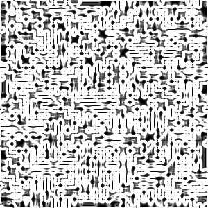
コマンドは選択範囲 (もしくはアルファ域) に旧式の電子回路プリント基盤の裏面のようなすじを描くスクリプトです。 あとで適当なグラデーションのグラデーションマップをかけるともっと見栄えがよくなります。
![[ヒント]](images/tip.png)
|
ヒント |
|---|---|
|
得られる効果については、 選択範囲を変な形にするとうまくゆくようです。 迷路のプログラムで選択範囲の扱いにある種の限界があるためです。 |
![[注記]](images/note.png)
|
注記 |
|---|---|
|
If the image is in indexed mode, this menu entry is disabled. |
![[注記]](images/note.png)
|
注記 |
|---|---|
|
This filter creates a gray level image in RGB mode. 描かれる回路は元画像に描かれている内容に頓着しません。 |
- 油絵化マスクサイズ
-
With this option you can set the option value of the Oilify filter in pixels (range 3 to 50). Larger values make lines more fuzzy. 17 is the default value.
- 回路種
-
乱数の種値を 1 から 3000000 の間で指定します。 デフォルト値は 3 です。
- 背景なし ([別レイヤーを生成する] を適用する場合のみ有効)
-
このオプションを有効にすると、 回路図の暗い画素に透明度が加わり穴となって下側のレイヤーが見えるようになります。 このオプションはデフォルトでは無効です。 別レイヤーを生成する オプションも合わせて有効にする必要があります。
- 選択範囲を解除しない
-
If an active selection exists when this script is called, you can keep the selection and its marching ants with this option. This option is enabled in default settings.
- 別レイヤーを生成する
-
このオプションを無効にしている場合は、 生成された回路図が活性レイヤーに上書きされます。 このオプションを有効 (デフォルト値) にすれば新たに設けられたレイヤーに回路図が描かれ元の画像は保たれます。
このスクリプトはつぎの手順で処理をしています。
-
First, draw maze with 5 pixels width pathways and walls with the 「Depth First」 algorithm. The pattern of maze is set by Circuit seed.
-
Oilify this maze with a brush of Oilify mask size.
-
Then apply the extract edge filter with Sobel algorithm, Smear option and Amount to 2.0, to the oilified maze image. This crowds high contrast winding curves like as a circuit map.
-
Finally, Desaturate the map with gray color in RGB mode.


