Just like for normal brushes, these animated brushes can also be either grayscale or color. For grayscale images, where the actual brush will use the current foreground color, you use white for transparency. For color images, transparent parts are used as such and when making brush strokes, the actual colors will be used instead of the foreground color.
To create a new animated brush, create either a grayscale or color image, based on whether you want the brush to use the user's foreground color, or the actual colors in the image. Then create the images for your animation steps. To save the brush into gih format, select → , name your work with the gih extension, and press the button. The following window is displayed:
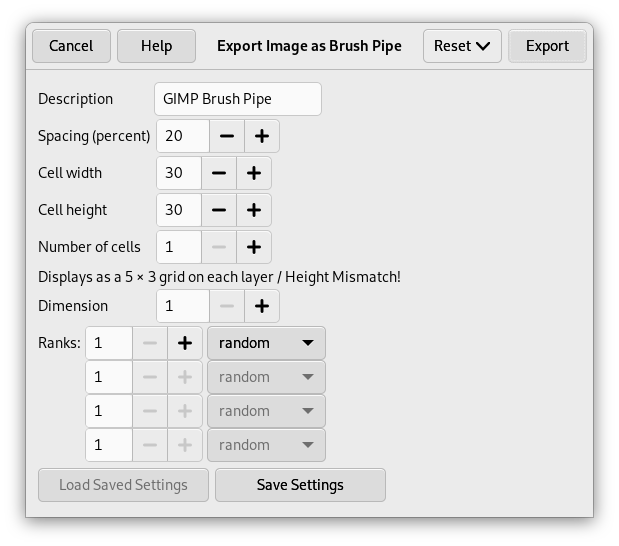
This dialog box has several options that allow you to select how your brush is animated.
- 間隔 (パーセント)
-
「間隔」とはポインターでなぞった描線上に並べられるブラシの刻印の互いの間隔のことです。 これはどんな描画ツールであっても、 ブラシをスタンプのように考えてください。 間隔が狭い場合はそのスタンプが互いに近づいて重なるので連続した描線に見えます。 逆に間隔が広い場合はスタンプが離れて並びます。 その良さは色ものブラシ (「ピーマン」みたいなもの) でわかります。 この値はブラシの「直径」を基底とする 1% から 200% までの範囲で指定できます。 100% がブラシの刻印ひとつぶんです。
- 説明
-
これはブラシにつける名前を記入するところで、 ブラシダイアログ上では モードなら各ブラシの右側に、 モードならば選ばれたブラシについてのみダイアログの上部に表示されます。
- セルサイズ
-
That is size of cells you will cut up in layers. Default is one cell per layer and size is that of the layer. Then there is only one brush aspect per layer.
たった 1 層の大きなレイヤーを細かくセルに分けて、 アニメーションするブラシの様々な相に割り当てることが可能です。
For instance, we want a 100×100 pixels brush with 8 different aspects. We can take these 8 aspects from a 400×200 pixels layer, or from a 300×300 pixels layer but with one cell unused.
- セル数
-
これはレイヤー 1 層あたりのセル数を定めます。 1 つの相に 1 個のセルが必要です。 既定では 1 つの相に 1 層だけレイヤーがあるとみなすので初期値はレイヤーの数と同じになります。
- 表示方法
-
この表示はセルをレイヤーに配置する様子です。 たとえばもし 4 層のレイヤーを使ってそれぞれに高さセルを 2 つ置く割合にすると、 この表示は
1行2列(各レイヤー)となるでしょう。 - Dimension, Ranks, Selection dropdown
-
これらは結構複雑です。 まずはセルとレイヤーの関係とその配置について説明するところから始めましょう。
GIMP starts retrieving cells from each layer and stacks them into a FIFO stack (First In First Out: the first in is at the top of the stack and so can be first out). In our example 4 layers with 2 cells in each, we'll have, from top to bottom: first cell of first layer, second cell of first layer, first cell of second layer, second cell of second layer, …, second cell of fourth layer. With one cell per layer or with several cells per layer, result is the same. You can see this stack in the Layers Dialog of the resulting
.gihimage file.つぎに GIMP はこのスタックをコンピューター式配列に記録します。 この配列は 1 次元から 4 次元までの 次元 に示された数値を用います。
コンピューター科学での 3 次元 (3D) では配列が myarray(x,y,z) のような形式になります。 2 次元を想像するのは簡単でしょう。 つまり紙の上の行と列の配列のことです。
3 次元の配列では行や列とは言わず 次元 と 並び といいます。 第 1 次元は x 軸、 第 2 次元は y 軸、 第 3 次元は z 軸のことを指しています。 それぞれの次元にセルの並びがあるのです。
To fill up this array, GIMP starts retrieving cells from the top of stack. The way it fills the array reminds that of an odometer: right rank digits turn first and, when they reach their maximum, left rank digits start running. If you have some memories of Basic programming you will have, with an array(4,2,2), the following succession: (1,1,1),(1,1,2),(1,2,1),(1,2,2),(2,1,1),(2,1,2),(2,2,2),(3,1,1),…, (4,2,2). We will see this later in an example.
各次元にそれぞれ桁数のように並びの数値を与えられるほかに、 これらには 選択 モードも与えられます。 使えるモードはつぎのとおり。
- Incremental
-
指定された次元から次元上での順序に従って位を選びます。
- Angular
-
与えられた次元から位を選ぶときにブラシが移動する方角を参考にします。
The first rank is for the direction 0°, upwards. The other ranks are affected, clockwise, to an angle whose value is 360/number of ranks. So, with 4 ranks in the concerned dimension, the angle will move 90° clockwise for each direction change: second rank will be affected to 90° (rightwards), third rank to 180° (downwards) and fourth rank to 270° (-90°) (leftwards).
- Random
-
与えられた次元から無作為に位を選択します。
- Velocity, Pressure, X tilt, Y tilt
-
これらは高度なタブレット描画のためのオプションです。
例
- 1 次元のパイプブラシ
-
「おいおい! そんなの何の役に立つの?」 答え: この例はこれからだんだんとグレードアップします。 次元も上げていきますから効果的なブラシもちゃんと作れます。
まずは 1 次元ブラシからはじめますが、 これでも選択モードのはたらきがわかるようになります。 下図のような配列を思い起こしてください。
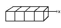
順を追ってゆきましょう。
-
Select → from the main menu.
Set Width and Height for example to 30 pixels.
In the Advanced Options, set the Color space to RGB color and set Fill with to Transparency.
Using the Text tool create 4 layers 「1」, 「2」, 「3」, 「4」. Delete the 「background」 layer.
-
Select → from the main menu to first save your image as an
.xcffile to keep its properties.Select → from the main menu to export the image as an animated brush with the
.gihextension.Export the image with a
.gbrextension in thebrushesdirectory located inside your personal GIMP configuration folder. -
In the Export Image as Brush Pipe dialog, provide a Description, set the Spacing (percent) to 100, set the Cell size to 30×30, set Dimension to 1, and set Ranks to 4, and the Selection drop-down to incremental. Then click the button.
-
In the Brush Dialog, click on the button
 .
.
Your brush appears among the other brushes. You can use it immediately, without restarting GIMP.
Select your brush. Select pencil tool for instance and click and hold with it on a new image:
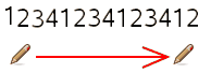
数字の 1 と 2 と 3 と 4 が順番通りに並んでいる
-
Take your
.xcfimage file back and export it as.gihsetting the Selection drop-down to random: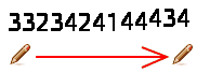
数字が順不同に並ぶ
-
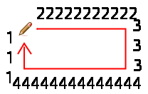
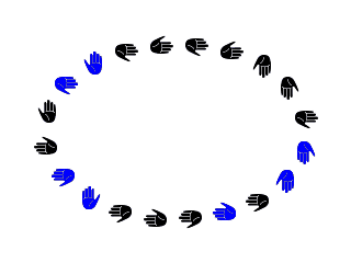
Now set the Selection drop-down to angular:
-
- 3 次元のパイプブラシ
-
さていよいよ 3 次元のアニメーションブラシをつくるところまで来ました。ブラシの方角によってブラシの刻印の向きを変えつつ左手と右手を交互に描き、 黒か青に無作為に色変りするブラシにします。
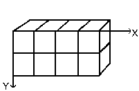
The first question we have to answer to is the number of images that is necessary. We reserve the first dimension (x) to the brush direction (4 directions). The second dimension (y) is for Left/Right alternation and the third dimension (z) for color variation. Such a brush is represented in a 3D array 「myarray(4,2,2)」:
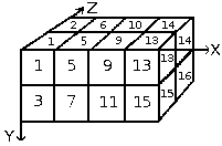
There are 4 ranks in first dimension (x), 2 ranks in second dimension (y) and 2 ranks in third dimension (z). Thus there are 4×2×2 = 16 cells. We need 16 images.
-
第 1 次元 x の形象を作成
Open a new 30×30 pixels image, RGB with Transparent Fill Type. Using the zoom draw a left hand with fingers upwards.[2] Save it as
handL0k.xcf(hand Left 0° Black).Open the Layers Dialog. Double click on the layer to open the Layer Attributes Dialog and rename it to handL0k.
Duplicate the layer. Let visible only the duplicated layer, select it and apply → → . Rename it to handL90k.
同様にして「
左手180黒」と「左手-90黒」も作ります。 -
第 2 次元 y の形象を作成
この例題では第 2 次元に 2 つの位を置き、 1 つめに左手を、 2 つめには右手を割り当てます。 左手の位はもうできています。 水平方向の鏡像反転を利用して右手の形象をつくりましょう。
Duplicate the handL0k layer. Let it visible only and select it. Rename it to handR0K. Apply → → .
同様に左手のレイヤーから相応する右手のレイヤーを作ってください
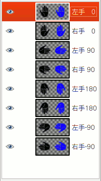
Re-order layers to have a clockwise rotation from top to bottom, alternating Left and Right: handL0k, handR0k, handL90k, handR90k, …, handR-90k.
-
第 3 次元 z の形象を作成
第 3 次元 z の形象を作成: 第 3 の次元には 2 つの位を設け、 ひとつは黒くもうひとつは青く塗ります。 黒の第 1 の位はもうできています。 しかも第 3 次元の形象はいずれも第 2 次元の形象を複製して青色に変えればできあがることはもうおわかりですね。 以上で 16 枚すべての形象が出揃うことになります。 しかし 16 ものレイヤーの列は管理がたいへんです。 そこでレイヤーに 2 つづつ形象を収めるようにしてしまいましょう。
Select the handL0k layer and let it visible only. Use → to change the canvas size to 60×30 pixels.
Duplicate handL0k layer. On the copy, fill the hand with blue using Bucket Fill tool.
そうしたら移動ツールを起用してください。 ツールオプションの アクティブなレイヤーを移動 にチェックを入れます。 青い掌をレイヤーの右側の区画に、 拡大ズーム表示の助けを借りながら正確に置いてください。
Make sure only handL0k and its blue copy are visible. Right click on the Layers dialog: Apply the command with the option Expand as Necessary. You get a 60×30 pixels layer with the black hand on the left and the blue hand on the right. Rename it to 「handsL0」.
他のレイヤーに対しても同じ手順を繰り返してください。
-
レイヤーを順番通り並べます
Layers must be set in order so that GIMP can find the required image at some point of using the brush. Our layers are yet in order but we must understand more generally how to have them in order. There are two ways to imagine this setting in order. The first method is mathematical: GIMP divides the 16 layers first by 4; that gives 4 groups of 4 layers for the first dimension. Each group represents a direction of the brush. Then, it divides each group by 2; that gives 8 groups of 2 layers for the second dimension: each group represents a L/R alternation. Then another division by 2 for the third dimension to represent a color at random between black and blue.
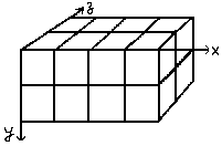
もう一つの方法は配列を視覚的に表現してみることです。 先に示した見方との相関図を下に示します。
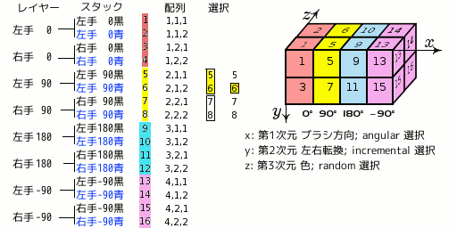
GIMP はどんなふうにしてこの配列を読み込むか?: GIMP が最初に読み取るのは第 1 次元です。 例題では (ブラシ方向: たとえば 90 度) に結びつけてプログラムされています。 90 度の位をみると、 黄色で示した第 2 次元では 選択によって左右の転換をしています。 そして第 3 の次元では、 無作為に色を選択しています。 よって最終的にレイヤーの順序は次のようにしなければなりません。
-
Voilà. Your brush is ready. Save it as
.xcffirst, then export as.gihwith the following parameters:-
間隔:
100パーセント -
説明:
手 -
Cell Size: 30×30
-
セル数:
16 -
次元:
3-
第1次元: 4桁、 選択: Angular
-
第2次元: 2桁、 選択: Incremental
-
第3次元: 2桁、 選択: Random
-
Place your
.gihfile into the GIMP brush directory and refresh the brush box (see steps above). You can now use your brush.
-
-
[2] Ok, we are cheating here: our hand is borrowed from https://commons.wikimedia.org/wiki/File:Stop_hand.png.


